A capacitor is a passive electric
element that accumulates energy in the form of electrostatic field. In
simple words, capacitor includes 2 conducting plates alienated by the
dielectric (an insulating material). The capacitance is inversely
relative to the alienation amid the plates and it’s directly relative to
the surface area of the conducting plates. Capacitance also relies on
the dielectric constant of the material alienating the plates.
The customary unit of capacitance is
termed as farad, abbreviated. This is a huge unit; other universal units
are known as microfarad, abbreviated 1 µF =10-6F (µF) & the picofarad, abbreviated 1 pF = 10-12 F (pF).
What is Capacitor?
“An
electric circuit element used to store charge temporarily, consisting
in general of two metallic plates separated and insulated from each
other by a dielectric, also known as condenser.”
Basics of Capacitor:
A
capacitor in general is like a battery. The common factor which is
there in a battery & capacitor is that they both store electric
energy. Capacitors store electrons inside it for any given time period. A
capacitor is a two-ended gear that includes 2 conducting units divided
by a non-conducting material. A capacitor actually comprise of 2
conducting surfaces on which energy is stored these surfaces are divided
by a lean insulating sheet which has an extremely huge resistance.
Capacitors in Series:
When capacitors are connected in series
the total capacitance is even less than any one of the capacitors’
connected in series, individual capacitance. If more than two capacitors
are connected in series, the whole outcome is of a solitary (equal)
capacitor which has the total sum of the plate space of the single
capacitor. As we very well know that a rise in the plate spacing, with
rest of the factors unaltered, outcomes in fall of capacitance.
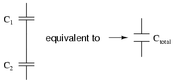
Therefore, the overall capacitance is
lower than any solitary of the individual capacitor’s capacitance. For
calculating the total capacitance of capacitors connected in series
formula is given below:-
Capacitors in Parallel:
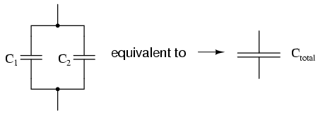 When
capacitors are united in parallel
the overall capacitance is the total of the solitary capacitor’s
capacitance. If more than 2 capacitors are linked in parallel, the whole
outcome is that of a solo correspondent capacitor which has the sum
total of the plate surface of the solo capacitor. As we have experienced
that an increase in the plate surface, while other essential factors
remain same, the outcome is an increase in the capacitance.The formula
to evaluate parallel resistance is same as for calculating total
capacitance of capacitors connected in series.
When
capacitors are united in parallel
the overall capacitance is the total of the solitary capacitor’s
capacitance. If more than 2 capacitors are linked in parallel, the whole
outcome is that of a solo correspondent capacitor which has the sum
total of the plate surface of the solo capacitor. As we have experienced
that an increase in the plate surface, while other essential factors
remain same, the outcome is an increase in the capacitance.The formula
to evaluate parallel resistance is same as for calculating total
capacitance of capacitors connected in series.
Types of Capacitors:
Capacitors can be employed in a number
of different manners in a variety of electronic circuits. Even though
their method of functioning remains precisely similar they can be
employed to supply a range of different circuit operations such as-
Coupling capacitor, Smoothing capacitor, Decoupling capacitor. There are
many other types of capacitors too that can be employed, maximum of
them are discussed below:
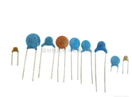
1. Ceramic capacitor:
Ceramic capacitor is found in many
appliances ranging from radio to RF. By far ceramic capacitors are the
most commonly used capacitors; this is because these capacitors are
cheap, reliable & their loss factor is much lower. These ceramic
capacitors are used in both leaded and surface mount formats.
Ceramic is most widely employed
capacitor which is employed in many appliances & electronic gears
now-a-days. At present ceramic capacitors are available in a wide range
of formats such as leaded constituents to surface mount technology.
Leaded version of disc ceramic capacitors is broadly accessible. These
ceramic capacitors are employed practically in each & every sort of
electric equipment. The exact performance of a ceramic capacitor
basically relies in kind of dielectric employed. Ceramic capacitors are
considered as workhorses of current capacitor world.
Ceramic capacitors are obtainable currently in 3 major types even though additional styles are also available:
- Leaded disc ceramic capacitors for throughout hole mounting which are resin layered.
- Multi-layer surface mount chip ceramic capacitors.
- Specialist microwave bare lead-less disc ceramic capacitors that are intended to be seated in a slit in the PCB and are welded in place.
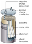
2. Electrolytic capacitor:
 This type of capacitor is polarized.
These capacitors are capable of offering higher capacitance value-
generally above 1μF, this type of capacitor is commonly used in low
frequency applications.
This type of capacitor is polarized.
These capacitors are capable of offering higher capacitance value-
generally above 1μF, this type of capacitor is commonly used in low
frequency applications.
Electrolytic capacitor has been employed
in many appliances for a number of years. The plates of this capacitor
are crafted from conducting aluminum foil. Owing to aluminum film the
plates can be made extremely thin and these plates are flexible as well.
Hence these plates can be packed at the end of the construction
procedure. The two plates included in this capacitor are a bit
different. The 1st one is coated with an insulating oxide sheet and a
paper spacer drenched in electrolyte is positioned amid them. The foil
insulated by the oxide coating is anode whereas the liquor electrolyte
and the 2nd foil operate as cathode.
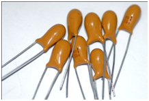
3. Tantalum capacitor:
These capacitors are even polarized and
they too supply extremely high capacitance value for their volume. This
kind of capacitor is extremely bigoted of being reversely biased,
frequently causing explosion when applied under pressure.
There are a number of benefits of employing tantalum capacitor are as follows:
- These capacitors have advanced volumetric efficiency
- These capacitors can be easily fixed in any sort of circuit boards.
- Tantalum capacitors have better frequency attributes
- Tantalum capacitors are extremely dependable, as they do not lose capacitance
Tantalum capacitors can be located in laptop, PCs, airbag circuitry in trucks & cars, mobile phones, pagers and a broad range of other devices.
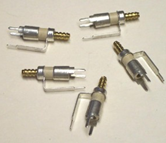
4. Variable Capacitor:
A variable capacitor is a kind of
condenser which helps in accumulating energy by generating electric
fields. The forte of this gadget is that the capability to preserve power can be altered either repetitively or deliberately through mechanical or electronic methods. Variable capacitor’s capacitance may be altered all through the lifetime of the gadget itself.
A mechanical structure is employed in the capacitor, which permit
altering the remoteness amid the different sets of plates, or
specifically, the surface of the overlying plate area, together with the
variable capacitance diodes. All these alter their capacitance behavior owing to the reverse voltage bias application.
Various types of variable capacitor are accessible. They are as follows:
- air variable capacitor
- vacuum variable capacitor
- variable tuning capacitor
- high voltage variable ceramic capacitor
5. Paper Capacitor:
Paper capacitors are prepared from paper
or oil-impregnated paper and aluminum foil sheets spin into a drum and
conserved with wax. These paper capacitors were normally employed but
are now substituted by the polymer or plastic made capacitors.

Some other capacitor types are as follows:
6. Silver Mica Capacitor:
This type of capacitor is not in use much these days but this kind of capacitor still supply very superior level of constancy, lower loss & accuracy where space is not a matter of concern.
7. Polystyrene Film Capacitor:
These are relatively cheap sort of capacitors but supply a close tolerance capacitor wherever required. These are tubular in shape; this is because the plate or dielectric sandwich is rolled collectively.
8. Polyester Film Capacitor:
These capacitors are employed where cost is a concern as they do not supply a superior tolerance. These capacitors are in general only accessible as leaded electric constituents.
9. Polycarbonate capacitor:
This type of capacitor is applied in appliances where performance & reliability is important. The polycarbonate film in extremely steady and allows superior tolerance capacitor to be manufactured which will uphold capacitors capacitance value over time.
10. Metalized Polyester Film Capacitor:
This is basically a polyester film capacitor the only difference amid the two is that in metalized polyester capacitor, polyester film is metalized. The metalized polyester film capacitors are usually only accessible as leaded electric constituents.
11. Polypropylene Capacitor:
This capacitor is employed when a superior tolerance is required than polyester capacitors supply. This capacitor makes use of polypropylene film for the dielectric. These capacitors are usually only accessible as leaded electric constituents.
12. Glass Capacitors:
This capacitor makes use of glass for the dielectric. This is an expensive capacitor but offer extremely superior level of performance in means of very low loss, higher RF current ability, no piezo-electric noise and some other salient attributes that make them perfect for several performance RF applications.
13. Super Capacitors:
Super capacitors come from a family of electrochemical capacitors. These capacitors are sometimes named as electric double layer capacitor (EDLC) or ultracapacitor. They do not comprise of any traditional solid dielectric. The capacitance value of a super capacitor is determined on the basis of 2 storage principles; these 2 principles contribute to capacitor’s overall capacitance.
Super capacitors are low in weight &
cheap as well that’s why it’s the most popular capacitor in market
these days. They are employed in most portable electronics & phones,
together with aircrafts & automobiles. The new technology super
capacitors are flexible and biodegradable.
Advantages of a Super Capacitor:
- No danger of overcharge
- Very high rates of charge and discharge
- High cycle efficiency (95% or more)
- Virtually unlimited life cycle – cycles millions of time -10 to 12 year life
- Charges in seconds
- Low impedance
- Super capacitors and ultra capacitors are relatively expensive in terms of cost per watt
12. Ultra capacitor: Ultracapacitors & super capacitors are one and the same, it has been explained above please refer.
Capacitor Capacitance Calculator:
This capacitance calculator evaluates the capacitance amid two parallel plates. The 1st calculator is metric, while the 2nd
is inches. Small valued capacitors can be engraved into a PCB for RF
purposes, but underneath majority conditions it is extra cost effectual
to make use of separate capacitors. A variety of dielectric constants
are given below.
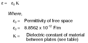
Equation:
C= K*EO*A/D, where Eo= 8.854×10⁻¹²
Where:
K- Is the dielectric constant of the material,
A- Is the overlying surface area of the plates,
d- Is the distance amid the plates, and
C- Is capacitance
A- Is the overlying surface area of the plates,
d- Is the distance amid the plates, and
C- Is capacitance
Capacitor Bank:
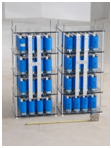
A Capacitor Bank is a cluster of a
number of capacitors of the similar rating that are coupled in series or
parallel with one another to accumulate electrical energy. The
resultant bank is then employed to work against or correct a power
factor pause or phase alteration in an AC (alternative current) power
supply. They can also be employed in a DC (direct current) power supply
to boost the ripple current capability of the power supply or to boost
the total sum of energy accumulated.
Capacitor banks operate on the similar
theory that a solitary capacitor do; they are intended to accumulate
electrical energy, just at a bigger capability than a solitary
appliance.
Application of capacitors:
Capacitors are used for a number of
purposes, it’s the most commonly found device in any sort of electronic
gadget. Each kind of capacitor has its individual advantage &
disadvantage and as a result, the applications of the capacitor can be
dissimilar. A number of capacitors are good for elevated frequency
utilization, while others can be employed for low frequency purposes.
Without a doubt it is essential to have the correct capacitor for the
precise usage of the circuit is to function appropriately.
- Timing – for illustration with a 555 timer IC to control the charging & discharge.
- Coupling – for illustration amid junctures of an audio system and to unite a loudspeaker.
- Storing energy – for illustration in a camera’s flash circuit.
- Smoothing – for illustration in a power supply.
- Tuning – for illustration in a radio system.
- Filtering – for illustration in the tone controller of an audio system.
Comments
Post a Comment